

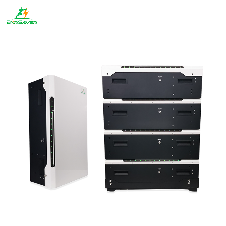


51.2V 1000Ah Power Stacked Lithium Battery Bank
Brand : EnrSaver
Product origin : China
Delivery time : 10-30day
Supply capacity : 5000 Pcs/Day
● Capable of High-Powered Emergency-Backup
● Highest Efficiency Thanks to a Real High-Voltage Series Connection
● The Quick Plug Connector Design Quick Wiring and Allows for Maximum Flexibility and Ease of Use
● Grand A Lithium Iron Phosphate (LFP) Battery: Maximum Safety, Life Cycle, and Power
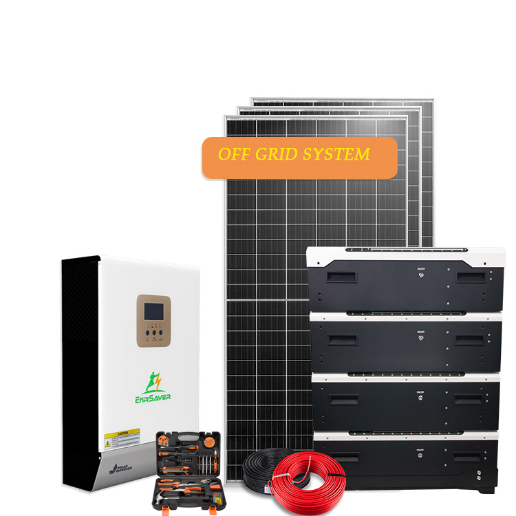
● Compatible With Leading High Voltage Battery Inverters
● The 51.2V LiFePO4 battery modules can be customized, also 50Ah and 400Ah capacity.

Battery Specification (@25±5°C°C)
NO.
Items
Characteristics
1.1
Nominal capacity
100Ah
1.2
Mix. capacity
98Ah
1.3
Nominal energy
1280Wh
1.3
Combination structure of battery
23140160-4S2P
1.4
Nominal voltage
12.8V
1.5
End of discharge voltage
10.8V
1.6
Standard charge voltage
14.6±0.2V
1.7
Float charge voltage
13.8V
1.8
Standard charge current
20A
1.9
Recommended charge current
<20A
1.10
Allowed Max. charge current
70A
1.11
Standard charge current
20A
1.12
Recommended charge current
<50A
1.13
Allowed Max. charge current
100A
1.14
Peak current
250A,10Sec
1.15
Internal Resistance
<40mQ
1.16
Weight
Approx.12.0kg±5%
1.17
Ex-factory capacity
Approx.50% SOC
1.18
Operation temperature
Discharge
-20C~60C
Charge
0C~45C
1.19
Storage environment
<1Month
-20〜+60C、5〜75%RH
<6Month
-10〜+45C、5〜75%RH
Recommend environment
15〜+35C、5〜75%RH
Electrical Characteristics & Test Condition
Testing Conditions: Ambient Temperature: 25±5°C; Humidity:45%~75%.
Normal charge: Charge battery under CC(0.2C)/CV(14.4V) mode until thecharge current reduce to 0.02C, and then rest for 1h.
No.
Items
Standard
Test condition
2.1
Normal capacity
3100Ah
After Normal charge, discharge @0.2C current to theend of discharge voltage.
2.2
InternalImpedance
<40mQ
@50% SOC @1kHz AC internal resistance test Instrument.
2.3
Short circuitprotection
Auto cutoff load when short circuit
Connect the positive and negative of this battery packthrough a lead with 0.1 Q resistance.
2.4
Dischargetemperature
Characteristic
-20C/25C>45%
-10C/25C>70%
0°C/25°C285%
Battery shall be charged according to standard charge, discharged at 0.5C to 10.8 V. Batteryshall be stored for 4 hours at the test temperature prior to discharging and then shall be discharged at the test temperature, The percentage shall be calculated using discharging capacity compared to the minimum capacity.
25°C/25W00%
55C/25C>95%
2.5
Discharge performance in normal temperature
Discharge capacity 0.2C >100% 1C >95%
2C>85%
When the battery is in the environment of25 C ±2 C, after standard charging, rest for 10min, and then discharge to 10.8v with 0.2C, 1C, 2C. Calculate the ratio of discharge capacity to rated capacity at each multiple.
2.6
Capacityretention rate
Capacityretention390% Capacity recovery 395%
Measure the initial state and capacity of the battery, after standard charge, then rest for 28 days, measure the final state of the battery; discharge at 0.2C to 10.8 V, measure the remaining capacity of the battery. After standard charging, the battery is discharged at 0.2C to 10.8 V to measure its recovery capacity. It can be cycled three times.
2.7
Cyclelife@D0D100%
32000 cycles
After Normal charge,discharge @0.5C current to theend of discharge voltage. Repeat above process untildischarge capacity reduce to 70% of initial value.
Circuit Protection
The batteries are supplied with a LiFePO4 Battery Management System (PCB)thatcanmonitor and optimized each single prismatic cell during charge & discharge, to protect thebattery pack overcharge, over discharge, short circuit. Overall, the BMS helps to ensuresafe and accurate running.
NO.
Item
Content
Parameter
3.1
Over charge
Over-charge protection for each cell
3.65±0.05V
Over-charge protection for battery
14.6±0.20V
Over-charge protection delay time
0.5-2S
Over-charge release method
Cell voltage<3.50±0.05V and battery voltage <14.0±0.20V or
Discharge current>2A
3.2
Over charge current
Charge over current protection 1
90±20A Charge current 90±20A
Charge over current protection delay time
300~800mS
Charge over current release
Cut load,Auto Recovery or discharge current>2A
3.3
Over discharge
Over-discharge protection for each cell
2.3V±0.10V
Over-discharge protection for battery
10.8±0.30V
Over-discharge protection delay time
0.5-1.5S
Over-discharge release method
Cell voltage>2.70±0.05V and battery voltage >11.2±0.20V or charge current >2A
3.4
Over discharge current
Discharge over current protection
Discharge current 300±30A
Discharge over current protection
50~150mS
delay time
Discharge over current release
Cut load,Auto Recovery or charge current>2A
3.5
Temperature
Charging high temperature protection
50±5°C
Charge Over-temperature release method
40~45°C
Charging low temperature protection
0±5C
Discharge over temperature protection
70±5C
Disharge Over-temperature release method
50~60C
Discharge low temperature protection
-20±5C
PCB temperature protection
90±5C
PCB Over-temperature release method
90±5C
temperature protection delay time
<10S
3.6
Cell balance
Balance Start Voltage
3.525±0.025V
Balance current
36±10mA
3.7
Short circuit protection
Short Circuit Protection Current
1050±200A
Protection condition
Load short circuit
Protection delay
450~800uS
Short circuit protection release
Cut load,Auto Recovery
Battery usage specification
4.1 When the battery is used alone, it can be used directly.
4.2 When the battery needs to be used in parallel or in series, each battery shall be fully charged according to the standard charging method before parallel or in series.
4.3 The maximum series number of batteries shall not exceed two, and the parallel number shall not exceed four.


All our products have certificates, mainly European certificates, CE, TUV, DEKRA, etc....more


